Finishing the story about the utility meters and its connection to Loxone. After articles about the electricity and gas meters I am focusing on the water meters here. Of course, there are water meters with pulse output already on the market, but in my case I wanted to read the data from the official meter I got from the water supplier.
The last from my utility meters to be connected to Loxone remained the water. Why I kept that so long on the to-do list is mainly because I was working with the option to have separate water meter for irrigation, or better said for filling the rain-water tank with water from the mains. That relates to the fact that 6000 liter tank is simply not big enough for everyday garden irrigation (even for small garden like mine), there is not enough rain during the summer period recent years. And because the watering systems are dependent on the water in the tank, I was looking for possibilities how to top-up the tank a bit when needed.
A bit of theory here 🙂
Just to explain the purpose of the planned secondary meter here. Please note, this might be very location specific so feel free to skip this paragraph. My water bill consists of two main parts. The consumed water from the main meter, and the calculated wastewater. The wastewater is calculated from the amount of water supplied, assuming that almost all water you use in your home goes back to the drain and has to be cleaned. As soon as you start using bigger portion of water from the tap for gardening purposes, it becomes not fair to pay for sewage the full amount calculated from the liters water consumed. Water used for your plants will never get back to the drain system, so there is no need to pay for water cleaning for that part.
In our country there is a law (#274/2001 Sb), saying that if the amount of tap water you consume and not drain is more than 30m3 a year, you are eligible to ask for official secondary meter to measure that amount to deduct it from the calculated wastewater amount. In other words, the secondary meter you’ll use for garden irrigation gives you the opportunity to pay just for the water, not for the sewage and obviously as a result you’ll save some money on the utility bill. However, the installation costs are to be paid by the customer, so there is some initial investment necessary in this space.
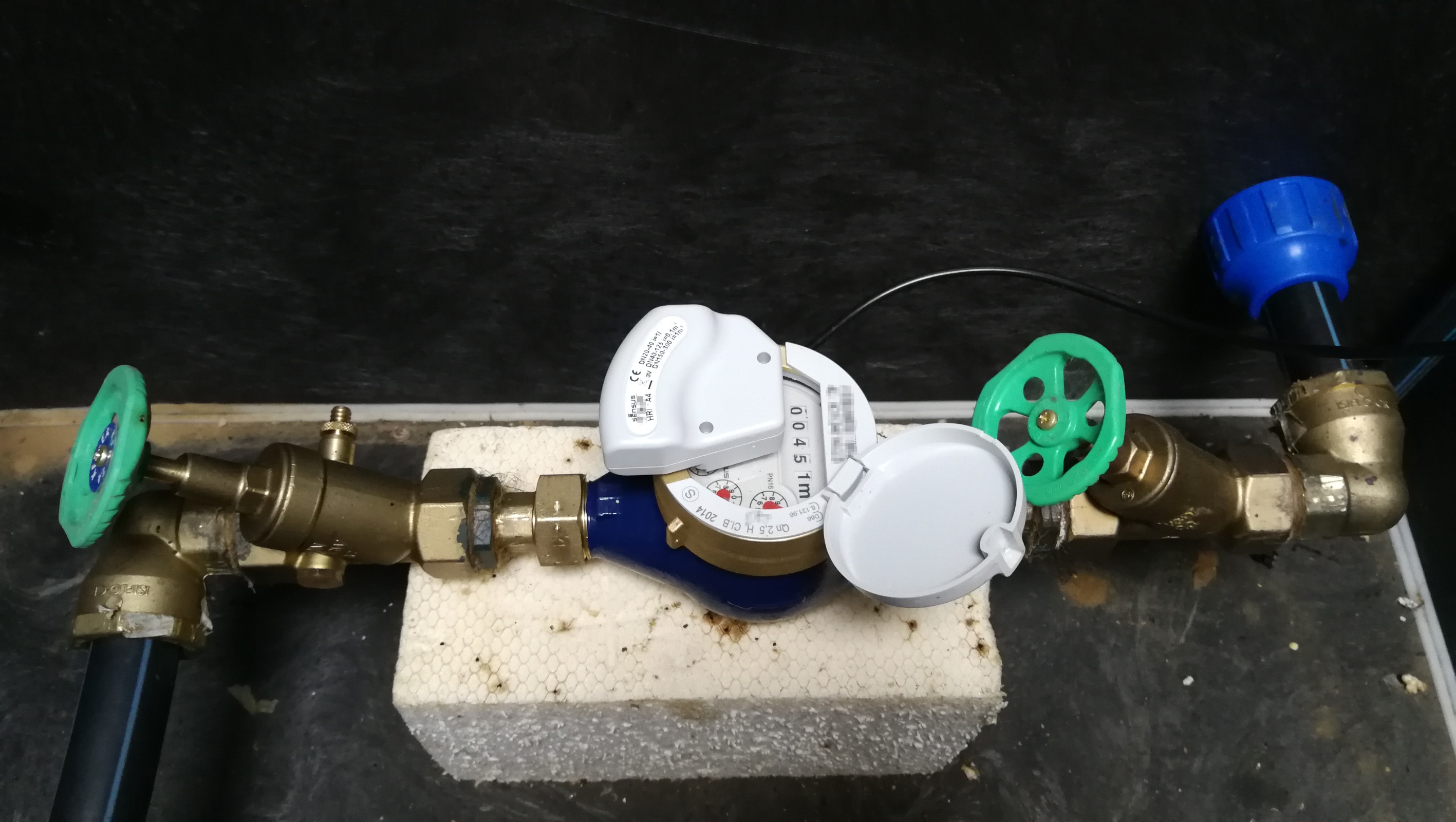
Now, my official water meter is located in the underground inspection water shaft. It is quite spacey pit given the fact that currently only two valves and the water meter are located there.

My plan was to add two more outgoing pipes for irrigation systems, and few cables to be able to control the valves and measure the water consumption. I have planned something like this from the very beginning, so it was not hard to modify and add wiring and pipes I needed. The schematics is illustrating the growth from the former simple valve – meter – valve setup into the more complex end result:

Please disregard the two outputs (one for the tank refill and the other to the irrigation directly). The second one is there just because my garden layout does not allow connecting the front garden part to the same watering system, so this is separately connected to the main water source without the use of the tank water.
So now, when everything is connected as planned I am able to:
- See the total water consumption similarly the electricity and gas, using the additional pulse reader for my water meter type
- I can use the automated garden irrigation system without being limited by the amount of water I get from rain
- The water level is primarily controlled by the ultrasonic water level meter connected to analog Loxone input (0-10V)
- As soon as the remaining water in the tank gets to the given minimum limit, Loxone will open the servo valve 1 to refill the tank by certain amount of liters that would be enough for the nearest pump consumption. (Obviously, we want to fill only the necessary minimum from the tap water and leave the rest of the tank empty for sudden rain.)
- The upper level for tank top us could have been set up by the value coming from the ultrasonic water level meter, but in my case I felt it is safer to have the flowmeters there for corner scenarios like:
- Identifying a leaking tank that would be constantly being filled otherwise
- Servo valve 1 or 2 not properly returning to closed position causing permanent paid water consumption
- I am now working on the config and triggers setup to alert me in any of suspicious scenarios which probably deserves another post later, once everything is fine-tuned and polished.
- I have also my front garden irrigation automated (though not from the tank system), but I can control the amount of water consumed there by setting the limit of liters coming from the flow meter 2.
- I am prepared for future additional secondary meter that would reduce my bill in case I consume more than 30m3 (30 000 liters) a year. That meter would be den equipped with some pulse output, either by design (if negotiable) or by similar additional HRI pulse reader as in case of the primary meter.
Parts I used for this to happen:
- Sensus HRI pulse reader https://www.iungo.nl/images/pdf/hri-installatievoorschrift-hri.pdf that works perfectly with Sensus 420 water meter I have from my water supplier

- Motorized valves suitable for 24 VDC, normally closed. This mainly because if anything happens (power outage, ..) water returns to the closed state. Same could be achieved with solenoid valves, but I do not recommend these for multiple reasons.

- Flow meters to get some sense of the flow in the pipe. Please note, even though these are rated to run on up to 24VDC, for constant usage the datasheet specifies 5-18V. A simple constant voltage regulator for 18V and two capacitors will do the trick

- Two regular manual valves
- Ultrasonic water level sensor with 0-10V output or cheaper Water level / pressure sensor with 0-10V out (these two solutions were still under consideration). Update: I just ordered the Water level sensor from AliExpress, will report once delivered and tested.
- And I used 4 digital, 1 analog input and 2 relays on Loxone Extension


How to connect these?
Sensus HRI pulse reader

Sensus 420 water meters (which is the model I have) do have prepared mounting points on the front so that the pulse reader can be easily installed.

Sensus HRI pulse reader is a “reading head” for multiple water meter types. It is pretty interesting device, I must say. HW installation is simple, there are two attached torx screws holding the reader on the mounting points in perfect position to be able to read the rotation of the meter’s wheel. the package also contains V-shaped replaceable plastic cover, that you can swap with the original one if you want to have the meter closed with the reader head mounted. If you ever decide to purchase this reader head, after making sure that it fits your meter, please pay attention to the pre-set configuration from the factory.
The variable “D” indicates the pulse weights. It could have the possible values for residential meters: D = 1 / 2,5 / 5 / 10 / 25 / 50 / 100 / 250 / 500 or 1000. If you have D=1 like I have, one pulse will equal one liter of water consumed. The other detail to make sure before purchase is the type. Depending on the order specification, HRI can be delivered in four different pulse modes HRI Pulse Unit: Type A1, A2, A3 and A4 HRI Data Unit: Type B1, B2, B3 and B4. For Loxone usage the A types are OK, the number indicates how are the two outputs being used (reversed flow pulses handling, tamper,…). I do have the A4 version, which gives me balanced pulses on the pulse output 1, and the second output is just used as a tamper contact. The device has four wires:
Green = 24V+
White = Pulse output 1
Yellow = Pulse output 2
Brown = Common ground
Connecting the white and yellow to Loxone’s digital inputs requires an additional resistor 4k7 Ohm as per documentation here.

It works the way that you will have log 1 when the sensor is off and log 0 when a pulse is detected by the sensor. In the software you can reverse this behavior so that when the sensor is on the input is high. To do this either use the NOT function block or negate wherever the input is connected to, or reverse the particular input using the small dot on it.
I should probably mention also the green wire on the HRI module, which can be used as an external power source. The sensor is equipped with 3V lithium battery with autonomy lifetime more than 10 years. With unbroken permanent power supply of 24VDC (max. 50VDC) unit lifetime is increased by more than 15 years. In case of external power failure the battery of the module takes over the supply. So connecting the green to the 24V+ can be recommended in this case. As always, please use fuses for all external devices to prevent accidental issues with your smart home infrastructure.
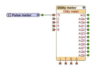
In the config the setup for the reader is simple, just adding the meter block and setting proper unit (liters instead of kWh), and the amount of pulses per liter (1 in my case). Alternatively you could have the consumption in m3 (which equals 1000 liters), so that you are in line with the figures on the utility invoice.
Motorized valves 24V
Moving from the sensor to the motorized valves for a second now. I am using the Mivalt’s MPA20-T motorized valves, normally closed (NC), workind with 24 VDC, but it can be purchased in multiple variants. These valves operate very nicely, the fact that it takes just one relay output on the Loxone extension is an interesting highlight. As these servo valves are in operation for just limited amount of time, I do not care about the static consumption in the opened state. These valves do have an equivalent for 230V as well, but I did not want to have mains voltage in the area surrounded by a lot of water equipment bearing in mind that the worst case failure scenario can result in flooding the complete underground inspection water shaft, including the power sockets and all cables.
Flow meters
Lastly the flow meters from Aliexpress, these work fine as well. Both are connected with reduced power voltage (not 24VDC from Loxone PSU) of 18 Volts, using a single constant voltage regulator and two capacitors as per datasheet. All fits in nicely into the double RJ-45 sockets, which I used as a connection points for all devices in the water shaft. The output is then going to digital inputs and meter block is configured to properly display supplied water.
Today I have everything up and running, just fine tuning the conditions when I should be watering and for how long. Work in progress is still the ultrasonic water level meter, so let me update this once completed. I hope you enjoyed reading this post.
Update August 12, 2018:
I need to correct my statement about the Chinese flow meters. These flow meters do send you 596 pulses per one litre water (+/-10%). Pipe of the G 1/2″ diameter can easily supply one litre water within 5 seconds which gives you more that 100 pulses per second! It turned out that Loxone was not able to register the amount of pulses per second and the numbers in the visualisation were completely wrong (very low compared to the reality).
As a result, the connection in the Loxone config needs to be changed.
- You need to make sure that your meter output is wired to a digital input of an Extension in this case.
- It is important that to use a digital input on the Counter input ‘C‘ of the Utility meter function block (not the trigger ‘Tr’)
- You need to set the input type to be used as a frequency counter and this can only be done on Extension digital inputs.To set the type in Loxone Config simply tick the box called ‘Frequency counter’ in the properties of the digital input. This will change the digital input into analogue, that instead of pulses provides the frequency value in Hertz.
- Finally you now need to define how many pulses per unit of measure your meter produces. In my case the flow meters generates 596 pulses per litre water.

This way you should be able to get the accurate figures from the flow meter into the statistics.
Visualization
So here are the charts you gonna see in the app or browser, to monitor your water consumption.


Why would’t you recommend solenoid valves in this application? And are you controlling the 24v directly from 24v digital output on the loxone?
Solenoids can be used as well, but I avoided these because:
1) They usually require AC not DC supplied and that would mean separate transformer only for this application
2) There is higher power consumption when powered, and that is for the whole period when engaged
3) They are sometimes more prone to issues caused by water sediments (but this probably case by case, because washing machines uses these without issues for ages. On the other hand some touchless faucets do suffer)
4) They close the flow at once and since the velocity and water pressure is rather high, they act as water hammer.
And regarding the valve control, Loxone does not have 24V digital output. See here: https://www.loxone.com/cscz/wp-content/uploads/sites/7/2016/08/schema_miniserver.png
I am using relay output, which triggers the 24V from a power supply for these external components. Also, for every outdoor thing I use fuses to protect the circuits and wiring and I fully recommend to do so. There are fuse holders for DIN rail mount available which are superb for this purpose.
Hi where did you buy the “Sensus HRI pulse reader”? Can`t find any online provider.
Thank you very much in advance
I got that from the local “plumbing” eshop, I do not have any other advice than to search for the item for you locally.
Hi!
This is a long shot since this post is pretty old, but I’ll ask my question anyway ;)-
I would like to use the Sensus HRI together with an MCU board to detect the pulse, count the water usage and integrate it in my home automation.
I did some experiments a few years ago, and everything was working fine, and I was able to detect the pulses from the sensor.
Now, I’m working again on this project, but the sensor does not seem to work anymore : it looks like the sensor does not emit any pulses.
Do you know if there’s any way to check that the sensor is working properly? Check the battery state? Maybe reset it ?
Thanks, on congrats for your interesting blog!
Hi,
thanks for the interesting post. I am solving a similar thing, how to plug Sensus HRI directly into Loxone. You mention that you have a Sensus HRI-A4 with 4 wires: white, brown, yellow and green. However, in the picture in your post and on the unit I have, there are only 3 wires, missing the green one. Can you advise how to wire this option directly into the Loxone.
Thanks for the help
Jan K.
Hi Jan,
Check the cable. I think the green wire was hidden under the black insulation (this wire has not been stripped and pulled out) if I remember correctly. Technically it should work also without the external power, but it is probably better to connect it to extend the lifecycle. The connection of the individual wires is described in the post.