The background
I have been posting few updates in this forum where I listed the options I was considering for water level measurement in my rainwater tank. I somehow strongly accentuated the ultrasonic method of measuring but never actually implemented it as the price of these sensors kept this item low on the priority list. Until I found this – The pressure based water level sensor. Some time ago I noticed these products already, but the ones I was looking at were not suitable for Loxone, these were with current output (instead of voltage), which would require additional HW converting it, not talking about space requirements in the cabinet, and so on. But now this is different.
Level sensor
Let’s have a look at the level sensor I purchased. It has robust stainless steel body, it can be powered by 9-36VDC and the output is 0-10V! Damn! Why haven’t I found this earlier 🙂 The sensor is great, but we will get there.

If you plan to order one of these, make sure you select the 0-10V variant and also provide additional details about cable length and measuring range. I am not sure about the detail how this can get customized, I was offered to choose the measuring range and cable length in whole meters, not a fraction (like 0-2 meters range, 3m cable). For my tank, the measured maximum depth is 108 cm (after that it starts overflow, event though there is a some additional space), so I was fine to order measuring range 0-1 meter, and 2 meters long cable.
I think I do not need to explain, how these sensors work, right? Unlike the ultrasonic ones which are mounted above the water and measure the time (and thus the distance) getting the echo from the reflection of the ultrasonic signal, the pressure based level sensors are mounted at the very bottom of the tank measuring the water pressure difference against the atmospheric pressure. Now, how can they know the reference atmospheric pressure that follows weather changes? The trick is in the cable which has a small ventilation hose that brings the external atmospheric pressure into the sensor. That’s why you need to specify the cable length before purchase and the connection point must be above the water level.

Installation
The biggest problem I had was unexpectedly the connection itself, where I wanted to use RJ-45 socket, but apparently I was unable to make the right connection in the connector. I temporarily solved this issue using fixed connection in the installation box, but for the future I want to have the sensor removable. I just need to find the right and robust connector for this purpose. Apart from that the installation is trivial, just three wire connection (24V+, GND, 0-10V output). A recommendation from my side again would be to fuse all external devices to prevent total system shutdown in case of any short-circuit failure on the 24V wires. Especially in the environment like this, which is extremely humid with sensor located permanently in the water, it is a good practice.
The wiring diagram I received was in Chinese, but there was nothing about the wiring colors for this type of sensor. However the seller responded pretty quickly, and confirmed the following wiring details.

Measuring accuracy
I have the sensor installed for about a month now and my biggest surprise is the accuracy of the measurement. This is totally beyond my expectations! The output from the pressure sensor is stable, without any wobbles in some range or something, and it registers every millimeter change in the water level height. Stunning results!
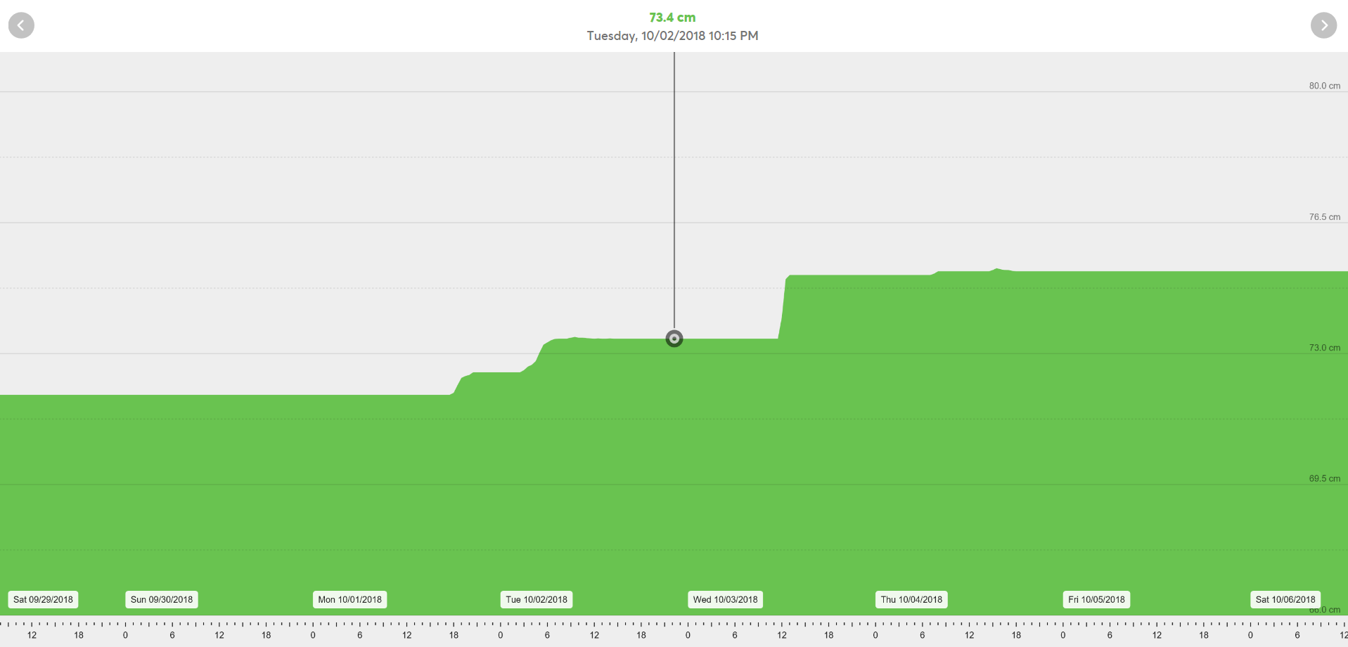
In my case the measuring range 0-1 meter, which means 0V on the output for empty and 10V on full (1 meter high water level) tank. Knowing the shape of the tank, I can also visualize the remaining tank water in liters. In the statistics then I can see not only the remaining amount, but also how much was consumed or added and when.
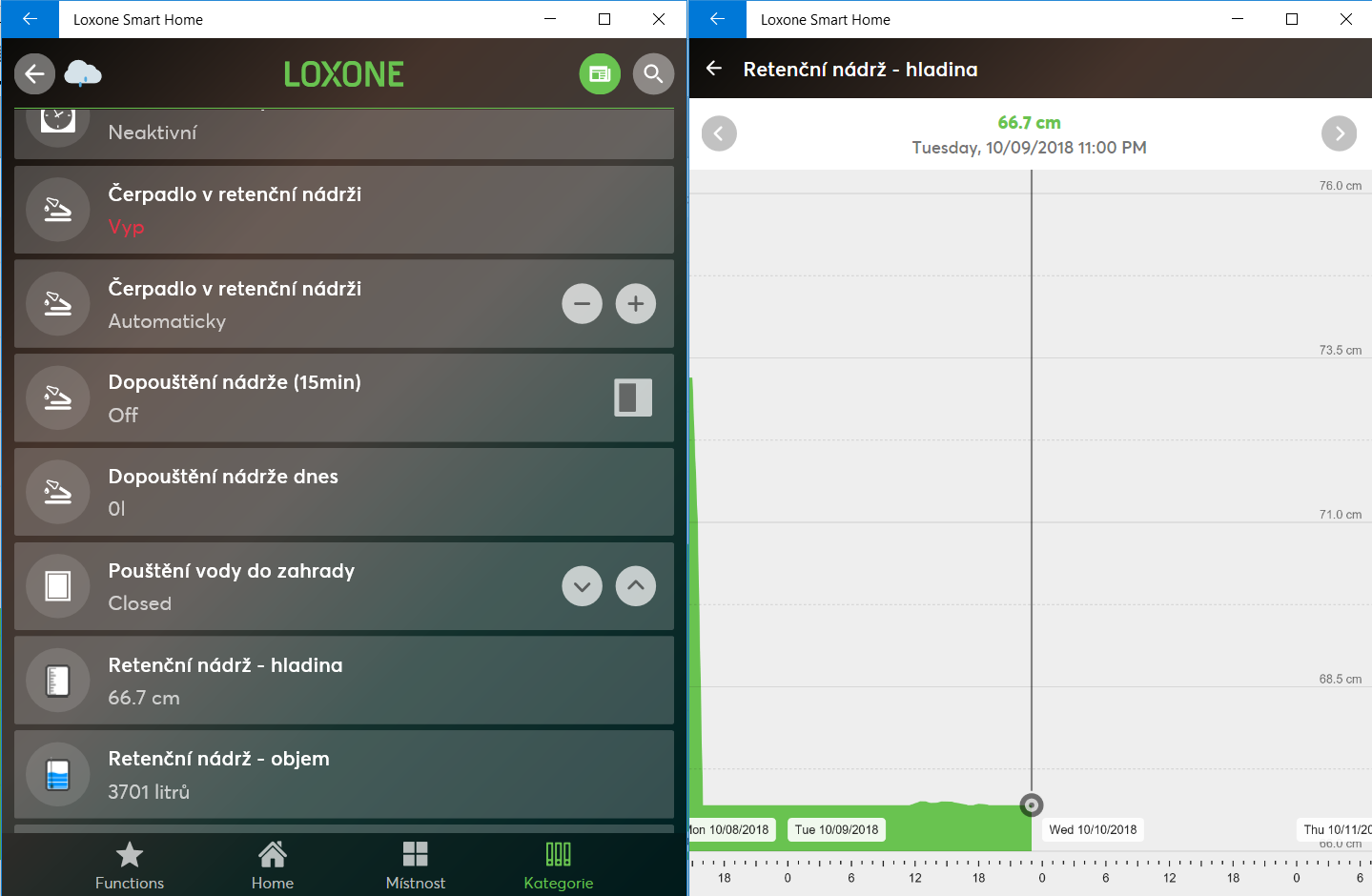
I have created an icon that illustrates the amount of water in the tank. This way it can be visualized on the dashboard. There are six levels I display using this icon, precise details are obviously in the chart.
Here are the assigned values:
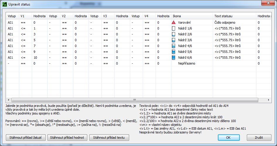
The sensor is giving me exactly what I needed, and the precision is higher than I would have expected.
On the roadmap
Few interesting outcomes can be generated using this. Firstly, while having the rain sensor installed, I could report the rainfall intensity, water consumed vs. stored. It is almost similar to what the energy meter block offers for solar panels, just applied to water. And lastly, better management of garden irrigation is something I will be working on.
Final word
I cannot fully compare the ultrasonic sensors with the pressure ones. Both will have its own domain where one or the other will dominate for particular reason. The advantage of the pressure type of measurement is the ability to measure in narrow spaces, where ultrasonic sensors would suffer from unwanted reflections. These can be created by several obstacles in the way (spider’s net, floating water) resulting in false alerts.
On the other hand, pressure sensors are laying at the very bottom of the tank all the time. They are impacted by the liquids they are in, and can degrade over time. I am really curious how long these last before something bad happens.
To sum this up, the price of this pressure water sensor was 50 USD incl. shipment. It is roughly one fifth of the price for the industrial reflective ultrasonic sensors I listed earlier.
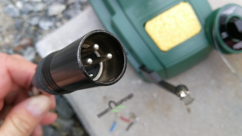
Update March 3rd 2019: After about a six months of operation the water level sensor status started appear as “disconnected”. Quick inspection revealed that the problem is in the cable connection located on a top of the tank area. I fully admit that the use of RJ-45 connector was a really bad choice for such humid environment. The contact pins were covered with massive corrosion.
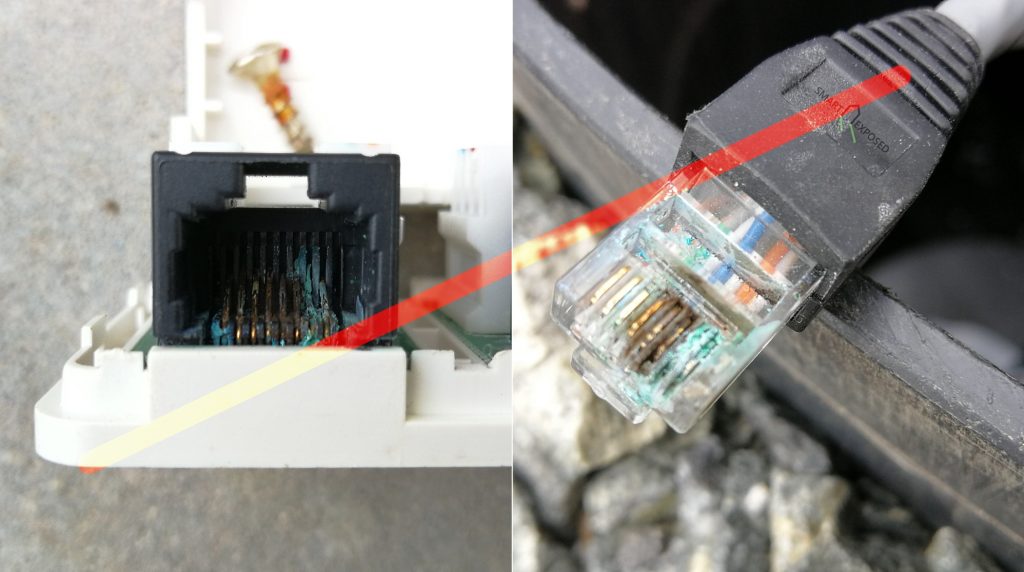
I rebuilt the connection box using the massive 3-pin XLR connector from Neutrik. We’ll see how long it will last.
What could we do better?


Super!
Many thanks Aleš!
Great find! I was looking for a sensor like this to start measuring the water level in my rain water tank.
Thanks. Great to hear you found this useful.
Thanks for the clear blog post.
Does the sensor need to be adjusted to the depth of my rain water tank? My tank is aproximately 2-2,5m deep, or do I need a sensor rated for the depth of the tank or will it work with one that is rated to 5m?
Thanks for the input
On the sensor there are no adjustments that can be made as far as I am aware. You need to buy one that spans over the depth (pressure difference) that gets then converted to O-10V signal out. The truth is that if your tank is 2.5 meter, using 5m sensor will have some impact on the accuracy as the output range will go only between 0V to 5V. For that reason I asked the seller to make a 0-1m depth with 2m cable for me, so try to ask if they could customize it for you either to 2.5m or 3m. The 5m will work as well, but as I said, it is better to have the depth interval with the full 0-10V scale.
Okay great, I will look into that. Thanks for the reply and I’ll keep following this blog!
You’re welcome.
Thanks for the blog entry!
Based on it, i too bought that sensor 🙂 Can’t wait to have it in operation.
I’m curious what you’re using as a fuse, though ?
Hi Gromit,
I am using these DIN rail mount fuse holders and I have each for any external component.
https://www.aliexpress.com/item/32772064483.html
You never know what can happen with either the device or the wiring. So this is to protect the rest of the circuits from sudden blackout.
That looks great!
I was just wondering how your loxone setup looks like. How do you get the data in a chart, and how did you manage to get your own icons in the loxone app?
I plan on using the ultrasonic sensor (i know it’s definately less acurate and more error prone), with an arduino feeding the data to loxone using virtual inputs. But still, I need that data in a chart, and want a live indication in the loxone app just as you have with your custom
Icon set.
Hi Frederik,
The functionality you asked about is pretty basic. The data charts are created for all values you measure once you select “Statistics” on the general tab of the block. You can specify the granularity of the data stored (from every change {data heavy} to some averages, in my case an average value for 30 minutes is stored.
Chart is then generated using these values. Please note, these values are stored on SD card, so it is vise to reasonably utilize that storage and also backup the data somewhere.
More details can be found in the KB article.
Custom symbols can be created or imported. In the Loxone Config tree, see Symbols/Status symbols and once you’re there you’ll find an option in the ribbon to customize the symbols. That opens a dialog box with all available symbols, the lower left corner shows a “+” that adds a new symbol. These symbol you create here can be used in the status block representing the value.
See here for more details.
Hello,
great post and investigation!
Can I use this sensor in ma septic tank? If not, what sensor do you prefer for such environment?
Interesting question. Personally I would rather use the ultrasonic sensors for such conditions. See here for some examples.
Can I use this type sensors to chiller water level indicator
Not sure what kind of water tank is that. It really depends on the water levels difference (highest, lowest), and the way you wan to use the output (how to convert this to some level indication).
One more thing. Are we talking about drinking water? If so, the you need to look for something that is certified and has not residual substances that can affect the water quality.
This is excellent and exactly what I am looking for, however, what did you hook the sensor up to? I assume some sort of audrino to measure the voltage on the output? I’m looking for something a little more plug and play for my rainwater tank that I can connect into Home Assistant.
The sensor I have has 0-10V output, so I am using Loxone’s analog input (0-10V) to read it. I am sure with Arduino this should be also possible somehow, but I haven’t tested this.
Hi Kops,
just curious…
Is the sensor still working ?
I would assume it get’s leaky after some time if it stays in the water 24×7…
Thanks for your update.
Christian
Hi Christian.
Yes, still working without any issue.
Hi, I’m planning on ordering the same sensor. My tank is 2 meter deep so I will need to order a custom range of 2m. Is the lenght of the cable also important? Does the connection has to be in the top of the tank or can I select a 5m cable and connect it in the nearby cellar? Thx
I think the end of the cable needs to be able to “breath” the atmospheric pressure, so it cannot be extended under the water or sealed for example. But having it on the top of the tank or in the cellar makes no difference unless your cellar becomes “pressurized cabin” by HVAC. The only thing to consider is the potential corrosion caused by high humidity, so if your cable can go directly to the cellar, it’s probably better I would say.
Hi, great post! I also got a pressure probe after reading your post, but I cant get it to provide logical readings. Mine has 4 wires, (black, red, blue and yellow). The supplier claims I should apply the voltage between red/blue and measure between red/yellow. In your case, I guess you apply the voltage between 24V+/GND and read between 10V/GND, right? Did you ever experienced unlogical readings?
Thanks.
Hi.
Thanks a lot to share this!
I have 2m of range.
I want to monitor the level under Home Assistant (on a Rasp Pi 4).
Which device can I use to connect the sensor?
Do you know if it can work with a TH10?
How did you wire it?
+24v and GND from PSU and 0-10v to analog input?
Yes correct. I just added a fuse to cut the 24V in case of any trouble, as the sensor is going to be placed outside of the house in a water tank and I do not want to have my house being shut down by any issue that might happen. But this is a general practice for all external devices. I am using these DIN rail fuse terminals, but there are for sure many others.
thanks!
Do you take the 24v from the loxone PSU or an external PSU?
i have 2, one on my main loxone and one on the RGB Dimmer tree i use for 2 WW-RGB strips on my staircase handle bars 🙂
do you also got the loxone configuration part on a file or so?
It doesn’t really matter if you use the main or external PSU, as long as the 24V- poles are connected between the two (common 24V minus for both PSUs). But In general, I use multiple PSUs for the whole house. But because I am switching off PSUs I don’t need 24/7 (RGB strips, …) then the infrastructure is using just one which is also protected against power outage.
The config I did myself.
Sensor works perfectly, i did get another wire layout
Red – +24v
Blue – GND
Yellow – Signal
Good to see you managed to make it work. It seems the manufacturers are somewhat creative in choosing the wires colors.
Dear ,
Still satisfied with the sensor?
Yes, works without any problem.
I’d love to hear an update on this and your garden irrigation project. I’m about to install a water tank and irrigation system. It would be super interesting to see if you got a lot of value out of integrating with Loxone. I have a Loxone system, I’m going to at least implement what you have done with the water level sensor, and I’ll also get Loxone to drive a servo that tops up my tank with mains water. Cheers and thanks!
Hi
Interested do have this build with my home automation. Particular interested to know which sensor you bought. Lots available not sure about quality and as you seems to be happy with yours like to stay with the same brand.
Thanks
I have a link in the post to the item I have purchased. So far it works fine. But you know, it is AliExpress so things might have changed in the meantime as sellers appear and disappear.
I have recieved mine pretty fast from the same compagny sensor world. I looks great and cannot wait to test.
The only problem is the color wiring. I have red,blue and yellow. I believe blue will be power – ,red is power + and yellow is output. But i have asked the compagny how to translate the colors. Await for an answer.
Documentation is only in chinese!
You can always translate Chinese documentations (or any other language) using the Google Lens app (Android) on your smartphone for example. It has ‘saved’ me countless of times.
Hello, may I ask how to connect the same sensor when I have wires: blue, white, black, red? Thank you
Great review! Your comparison of ultrasonic vs. pressure sensors is very insightful. The accuracy you achieved with the 0-10V sensor and the Loxone integration is impressive. The tip about avoiding RJ-45 in humid environments and switching to XLR is especially useful.