This post is an update of an earlier article I did for garden irrigation. The main reason for this update is an additional section/solenoid valve added to the system which I want to control with Loxone. In the previous design I used three of the extension relays outputs (one relay per solenoid). With the newly added section I would be at 4 relays just for the solenoids controlling the garden irrigation, not talking about the pump and other related stuff.
The idea here is to move away from Loxone relay outputs and use the four available analog outputs from the Loxone Extension instead. This way I will be feeding external relays to control the garden irrigation. I this example I am using external box with separate switch board I made as a part of the solution for solenoid valve control, but the principle can be used for any other similar applications.
Now, the reason for this all is not to save a couple of Euros for another Extension, but to expand my current setup, without to have to throw away everything I have done so far. My cellar (decentralized) mini cabinet has a just two small DIN rows and there is no way of fitting an additional Loxone component. With the solution below I was actual able to free last three relays and move the solenoid control towards the analog outputs 0-10V which I do not use in that particular place and that extension.
Danger! This design of the board below and the circuits wiring combines low voltage and mains 230V on the same board! This can represent serious hazard for people without proper understanding of the principles and technical knowledge. This is not a toy for kids!
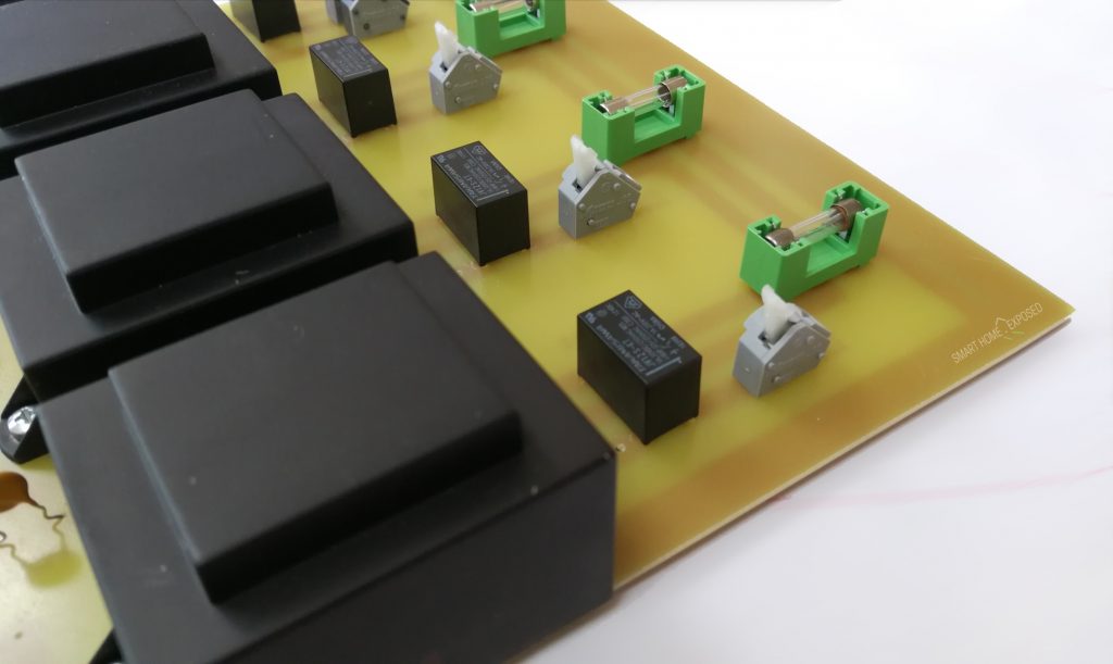
The principle is easy. Instead of using the Loxone Relay outputs I have added four relays to my custom control board which I modified a bit, and using the 0-10V signal from Loxone’s analog output I will be able to control all four of these external relays. The only limitation is that from Loxone’s analog output we can draw 20mA maximum! This limits the selection of the potential relay candidates to usually a smaller components. But at the same time we need a relay to be able to switch the mains voltage of 230V. These are two constraints that are almost mutually exclusive. Relay that has tiny DC coil to not consume much (less than 20mA) but at the same time the contacts robust enough to survive some load with the space in between that can safely interrupt 230V circuit. My final candidates were:
- Takamisawa JV-12S-KT U=12V DC, I=17mA, switching 230V! / 5A max. [Price slightly over 1 EUR]
-or- - FINDER 34.51.7.012.0000 U=12V DC, I=14mA, switching 250V AC / 6A max. [Price slightly over 5 EUR]

So to describe the design of the circuits, there are four identical sections each for one solenoid. Each section is connected to 230V AC (!) and controlled by 0-10V output from Loxone, triggering corresponding relay to turn the relevant section ON/OFF. The relay coil is rated for 12V DC (works perfectly on 10V from Loxone’s AO) and the relay contacts are switching the mains voltage for each mini-transformer to get the 24V AC for solenoid valves. The thing is that the transformers are in operation only if the irrigation section is in operation. Yes, I could design it with just one common transformer and switch the individual outputs, but then the transformer would need to be bigger (taking into consideration the load in case multiple sections are in operation, and would be working 24/7 unless an additional relay would be added to switch it ON/OFF.
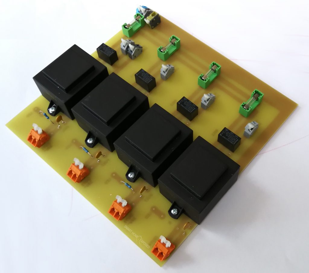
In this update I am adding one more section (previously I had 3 and used relays in the Loxone Extension, now I will have 4 sections and will use Loxone’s analog outputs instead) so I had to change the PCB to be able to fit the four relays there and also make a space for fourth transformer 230V AC –> 24V AC, or better said fourth channel.
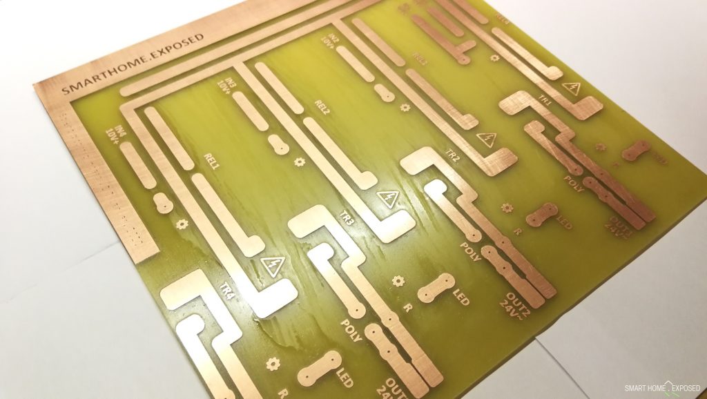

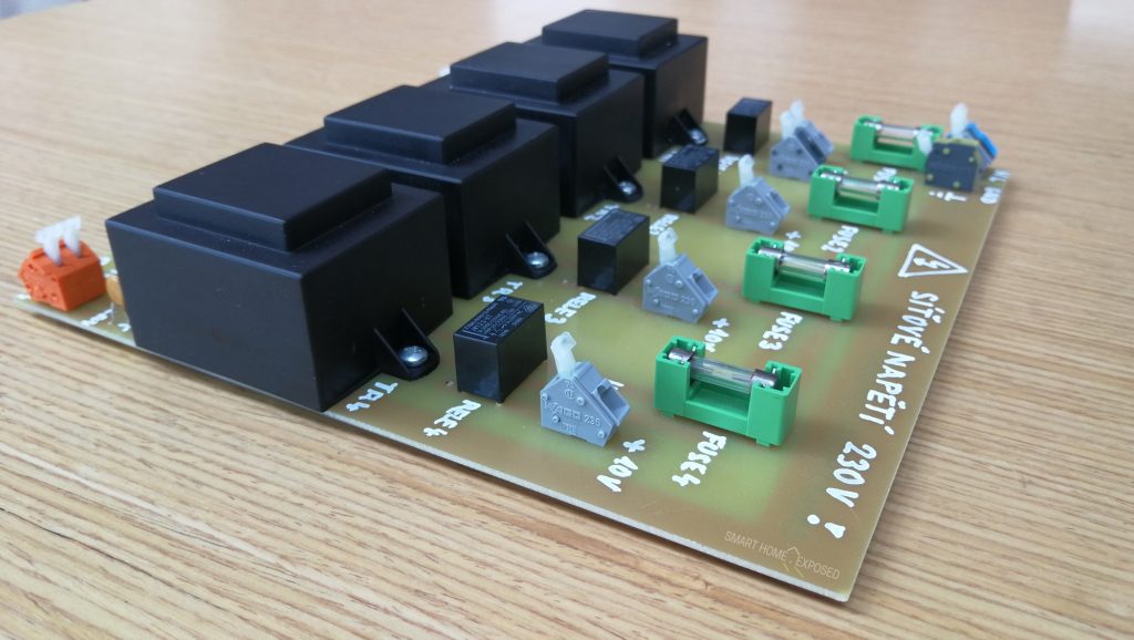
For each channel there is 230V fused input (50mA slow fuse) for the transformer, that is switched with each relay. Input for the relay is the 0-10V signal coming from Loxone Extension analog output. As I said, the 12V relay works flawlessly on 10V input, and the coil consumes also a bit less miliampers than the nominal DC current at 12V.
Then on the output from the transformer I have the same circuit schematics as it was in the first version of the board. There is a poly-switch (auto-recoverable fuse), resistor for LED indication, and output terminal for solenoid connection.
Finally the size of the board is the same as the previous to fit the same box. I know that this upgrade was a bit more-than-necessary-hassle, however this way I got back some free relay outputs from my extension I have in the cellar, and expanded the irrigation from three to four sections in my garden.
In the Loxone config, the use of the analog (0-10V) outputs called AQ is in this case similar to the relays outputs Q. The only difference is to apply proper correction (in the setting of the AQ, so that:
- input 0 = output 0V
- input 1 = output 10V
This way we can get just 0 Volt output when the output is off, and 10V when there is logical 1 in the program. And this is all, no further changes necessary. I hope someone finds this usefull.
Update: I have received an interesting comment regarding the design. The comment concerns the fact, that I am connecting relay coil onto Loxone’s analog output directly and that I should have added freewheeling diode to protect the analog output from the energy stored in the relay’s coil when you switch the current off. Without the diode, the energy has no place to go and will cause a large voltage spike which could be also destructive to the inner circuits inside Loxone.
I really thanks a lot for such comment. Adding a diode is indeed a good practice and I am going to add these into my board as well. If you’re interested how to do it, see the following schematics I received:

The diode (in red) is in parallel with each relay coil in the opposite current direction. For more technical details please check this info. Many thanks to Mark F. for vital contribution to this update.


Hello,
Thanks for your great article, indeed.
Just to inform you that the link to the image with the diode is broken.
Thanks a lot.
Ciao
Thanks for the flag Marc. Fixed now! 🙂
Hi Kops,
Are you willing to share your PCB design and parts (resistors, …)? Did you use EasyEDA to produce your PCB? In case, I implemented a block function in C for Loxone, that subsumes into a single block function all irrigation parameters, including weather forecast, ultrasonic sensor for water level, moisture sensor, anemometer, rain sensor, …).
Thanks
Hi Marc,
sure, I can share the PCB design, however I didn’t use any Eagle like PCB editor. All the free versions I tested were lacking the parts I wanted to use, so I ended up to do it in a normal graphical editor. Let me upload what I have and paste a link.
Stay tuned.
Hey, thanks a lot for your reply and for sharing. So cool. I started to play with EasyEDA. Let me see if I can produce a decent PCB of your project. I’ll keep you informed.
Ciao
Sorry for the delay, I had some difficulties to find the latest version of the PCB design. I only have raster version of the board, you can find it here. https://smarthome.exposed/wp-content/uploads/2021/01/irrigation_pcb_v2.1.png
It is far from being professional, mainly because of the tools I could use. But it serves the purpose I hope.
Thanks for the PCB design, indeed. On my side, I’m gently achieving the design on EasyEDA (based on yours). I’ll share as soon as the latter will be neat. Thanks again. Ciao