Back in August 2018, I wrote a detailed post about Connecting your water meter to Loxone. In that article, I explained how I manage automatic refills for my water tank, and I gave a very specific recommendation when it came to choosing the hardware:
“Motorized valves suitable for 24 VDC, normally closed. This mainly because if anything happens (power outage, ..) water returns to the closed state. Same could be achieved with solenoid valves, but I do not recommend these for multiple reasons…”
Well, fast forward eight years.
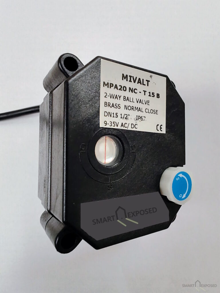
Those motorized valves (specifically, the Mivalt MPA20 NC model) have been sitting in my cellar, quietly doing their job. But recently, one of them failed to close.
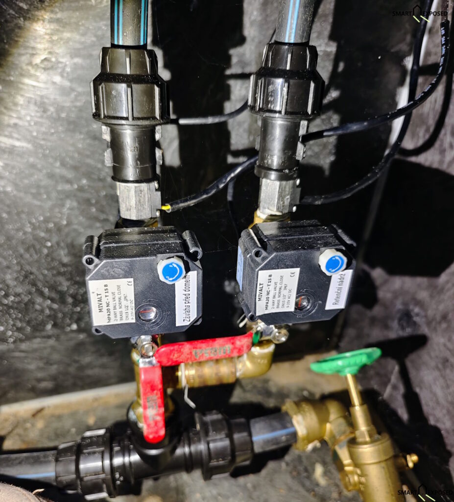
It turns out that even “fail-safe” smart home components have a wear-and-tear expiration date. Today, I want to talk about how these valves actually work under the hood, how a crucial smart home safety layer saved my wallet, and how you can service and upgrade these valves yourself with a soldering iron and a €3 replacement part.
The 70,000 Cycle Myth vs. Real Life
If you look up the datasheet for the Mivalt MPA20-T series, the manufacturer claims a lifetime of 70,000 cycles.
In my setup, these valves live in a cellar with a rock-steady temperature. They experience roughly 100 cycles a year. If you do the math:
100 cycles/year × 8 years = 800 cycles total
That is barely 1.1% of the rated mechanical lifetime! So why did it fail?
The weakness isn’t the mechanical gearbox or the motor. It is the chemistry inside the electrical energy storage.
How Normally Closed (NC) Motorized Valves Work
While I am using the Mivalt MPA20, this guide is also 100% applicable to the Tonhe A20-T15-S2 and the CWX-25S (often sold under brands like U.S. Solid or MISOL), as they share this exact internal design. Unlike a solenoid valve (which uses an electromagnet to actively fight a spring and constantly gulps down power while open), a motorized valve is much more elegant.
When you apply 24VDC, an internal electric motor turns a gearbox to slowly open the valve ball. Once open, it draws almost zero power. But if it has no return spring, how does it close when the power is cut?
The answer is stored electrical energy. Inside the valve casing, there is a small circuit board featuring a Supercapacitor (or SuperCap).
When the valve is powered on, it charges this supercapacitor. When the smart home cuts the power (or the house experiences a total blackout), the internal circuit detects the voltage drop, switches its power source to the SuperCap, and uses that stored charge to run the motor in reverse, sealing the valve shut.
If you are surprised, that a capacitor is capable of delivering energy to run a small motor closing the valve, lets do a quick calculation here to understand the energy stored in that capacitor.
The energy stored in a capacitor is calculated as Energy = 1/2 × C × V². The result is in Joules, which in electrotechnical terms is exactly equal to Watt-seconds (Ws).
The manual for these valves (MIVALT and the identical Tonhe A20 or CWX-25S models) states that it takes roughly 6 seconds to fully rotate the valve (in my case it is much quicker now). This allows us to calculate the average power available to the motor during that critical closing window:
For the original factory 1.5F capacitor:
- Total Energy: 0.5 × 1.5F × (5.5V)² = 22.7 Watt-seconds
- Available Power over 6s: 22.7 Ws ÷ 6s = 3.78 Watts
For the upgraded 2.5F Viking capacitor:
- Total Energy: 0.5 × 2.5F × (5.5V)² = 37.8 Watt-seconds
- Available Power over 6s: 37.8 Ws ÷ 6s = 6.30 Watts
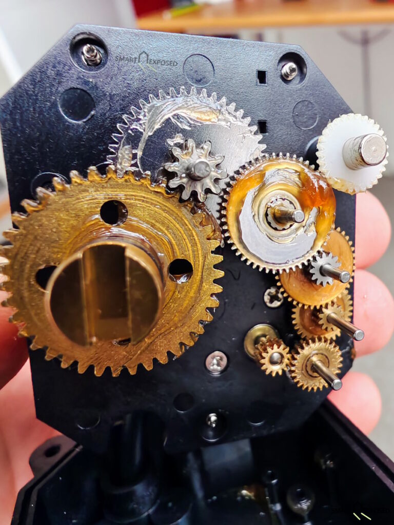
While 3.78 Watts might not sound like much, this is where the gearbox is doing its magic. Most of these mini-motorized valves draw between 2W and 5W while in motion. The torque goes from the small high-speed motor through a series of seven cogwheels to the ball valve shaft. This massive gear reduction transforms that modest electrical power into significant mechanical force, more than enough to turn a brass ball against water pressure, provided the capacitor is healthy.
However, if the capacitor loses even 30% of its capacity due to age, that available power drops to about 2.6W. This is the “danger zone” where the motor might stall if there is any mineral buildup or friction in the valve.
Anyway, the capacity of 1.5F is pretty insane in such a small form factor. I remember electrolytic capacitors from my childhood having 3000µF and the size of a Coke can, but that was different technology back then. Today, the chemical reality remains: supercapacitors are wear items. Over nearly a decade, the electrolyte slowly degrades, the equivalent series resistance (ESR) rises, and the capacity drops. Eventually, the motor no longer receives enough sustained power to fight through the mechanical resistance of the valve and finish a complete closing cycle.
When a “Fail-Safe” Fails: Why You Need Secondary Checks
A motorized valve failing to close is a silent hazard. Your smart home software thinks the valve is closed because it turned off the relay. In reality, the valve remains partially or fully open, and water continues to flow indefinitely.
I was incredibly lucky. When I set up this system, I didn’t rely solely on the assumption that “normally closed” meant 100% reliable. I installed cheap flow meters on the lines, integrated into Loxone.
On that particular day, the SuperCap was half dead, Loxone switched off the valve relay, but the flow meter kept ticking. My Loxone configuration immediately flagged this anomaly: Water flow detected when the valve is expected to be shut.
In my specific case, this valve controls the refilling of a tank equipped with a physical overflow drain. If I had not done anything, the excess water would have safely gone down the sewer, meaning no water damage would have occurred. However, had I not caught it quickly, my water bill would have been a painful surprise.
The key takeaway: Never trust a single point of safety. If you use motorized valves for critical water mains or automatic filling systems, always implement a secondary check, like a pulse water meter, flow sensors, or flood detectors, paired with an automated main shut-off valve that can isolate the branch if an anomaly is detected!
The Weakness Signals & Servicing the Valves
Once I diagnosed the failure on the first valve, I noticed that my second, identical valve was also acting up. It hadn’t failed completely yet, but it was showing classic “weakness signals”, specifically, the motor was noticeably slowing down and sounding strained during the last few seconds of its closing cycle.
I decided to pull both valves out of service for a quick workbench overhaul.
Sourcing the Replacements
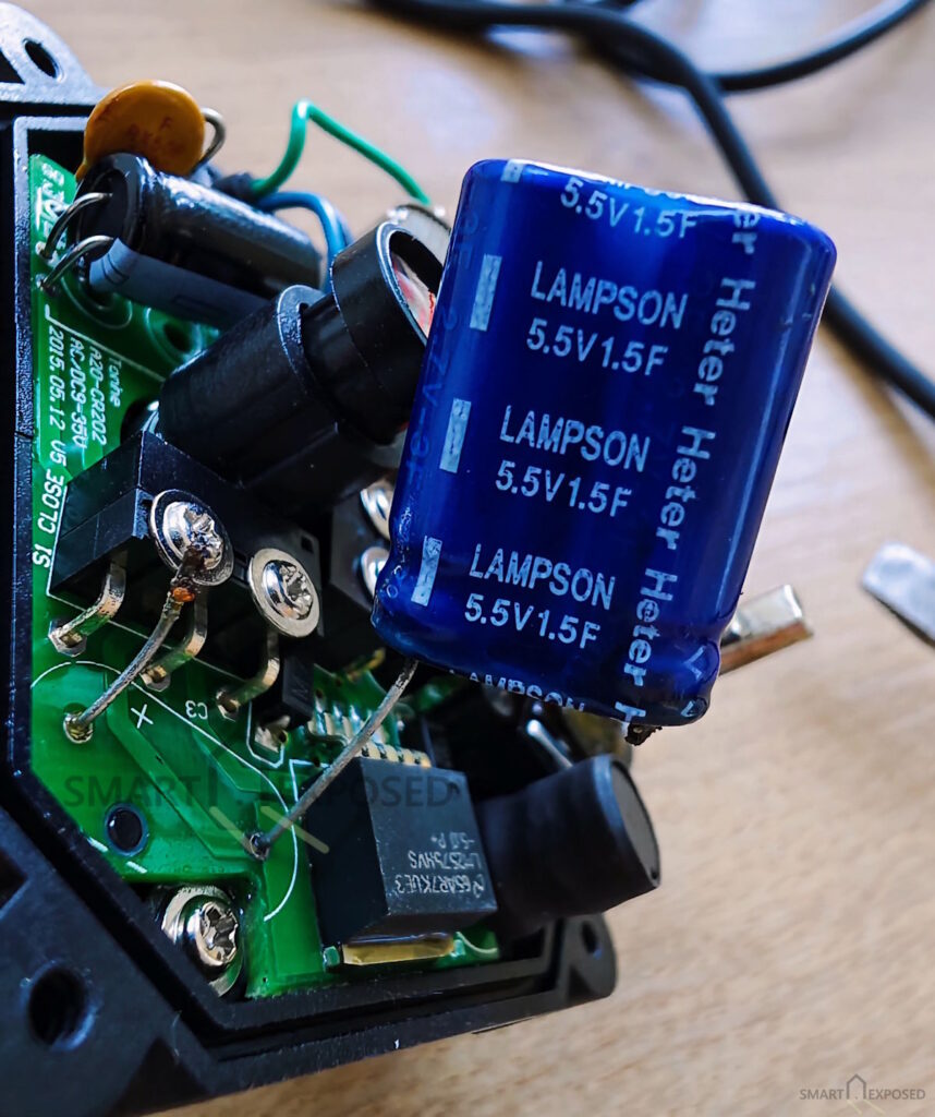
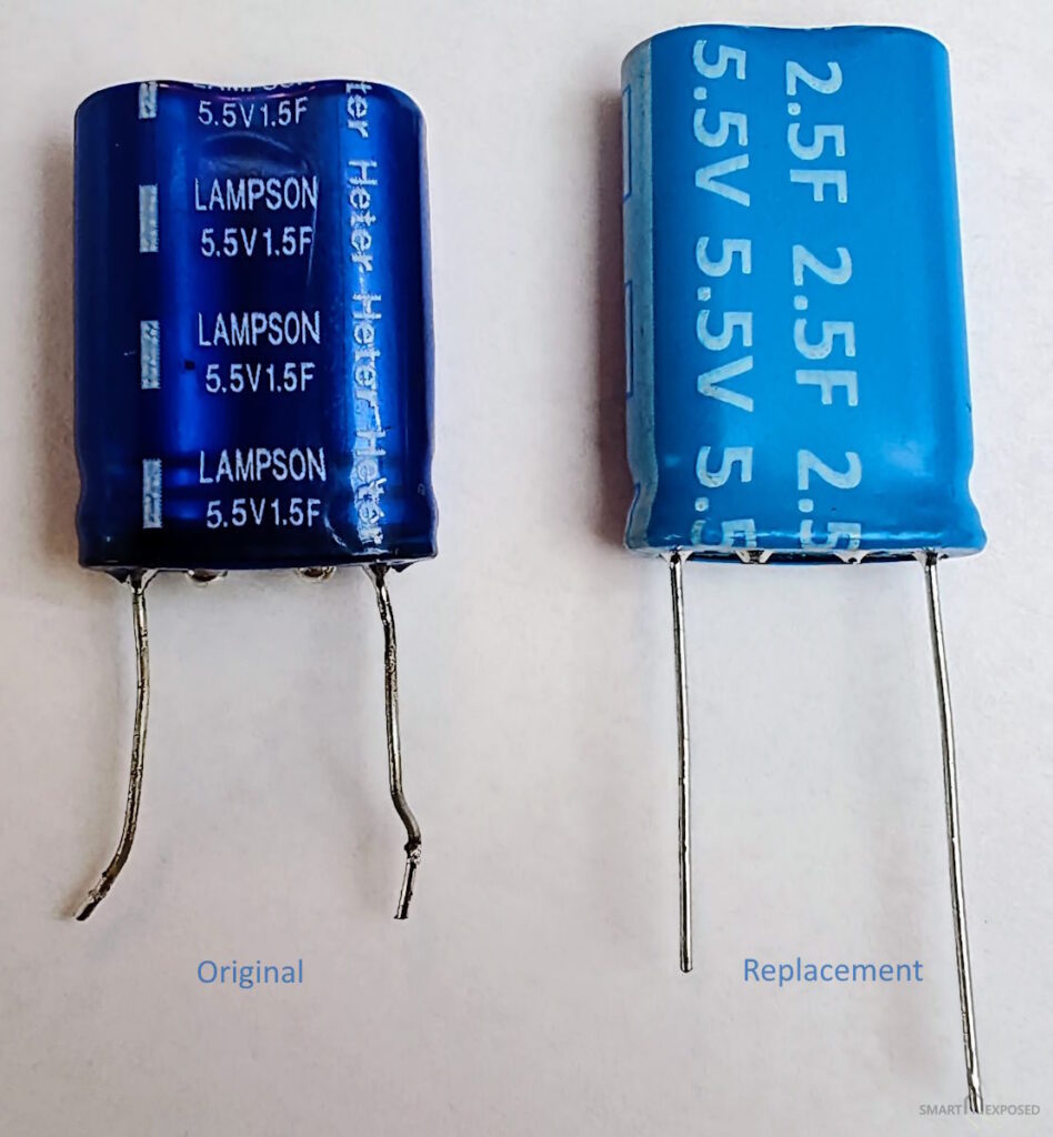
The factory-installed SuperCap is a Lampson 5.5V and 1.5F, so direct replacement found locally would probably be:
- HY25R58E22V155RN (by CAP-XX)
- Specs: Radial THT, 1.5F, 5.5VDC, 250mΩ ESR, dimensions: 8.5 x 17 x 22 mm.
- You can find the exact original part on TME here.
However, since I had the housing open, I decided to upgrade. A larger capacity means more stored energy, which gives the motor a stronger closing torque and provides a massive safety buffer as the capacitor ages over the next decade.
I found a slightly larger alternative that still fits perfectly inside the plastic valve enclosure:
- SC5V5Z255M (by Viking)
- Specs: Radial THT, 2.5F, 5.5VDC, dimensions: 17 x 25 x 8.5 mm.
- You can buy this upgraded version on TME here.
Step-by-Step DIY: Replacing the SuperCap
Replacing the capacitor is a very straightforward solder job that takes about 15 minutes per valve, provided you have basic electrotechnical knowledge and decent soldering skills.
Step 1: Open the housing
Unscrew the plastic cover of the Mivalt actuator, there are four Philips screws. Before you can remove the plastic cover, you also need to remove the manual operation knob. Small screw is located under the central sticker on that knob.
BTW, I didn’t realize until now that the valve can be manually operated using this knob (marked S=stop and O=open). If you just try to rotate it, nothing happens, you have to PULL the knob up first. This disengages the motor so you can operate the valve by hand without the internal gears fighting you. There was absolutely no word about it in the manual.
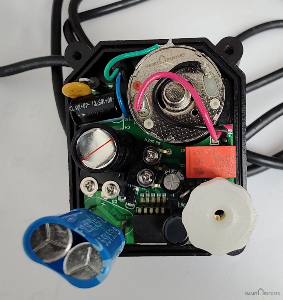
Once the plastic knob is removed, carefully lift the cover to expose the control board and motor assembly.
Step 2: Locate the old capacitor
The old capacitor is the large blue two cylinder block soldered on long contacts to the board. Take a mental note (or a photo!) of its orientation.
CRITICAL SAFETY NOTE: Supercapacitors are polarized. One side of the capacitor has a stripe indicating the negative (-) lead, and the circuit board will have a corresponding mark (often a minus sign or a shaded half-circle). You must install the new capacitor in the exact same orientation. Installing it backwards will destroy the component and could cause it to pop or leak.
On my board there was the + pole clearly visible, so there was no doubt how to position the replacement super-capacitor.
Step 3: Desolder the old component
In order to get to the bottom of the circuit board, you need to remove few more screws. There are 2x two screws holding the micro-contacts for the end positions, and then additional two or three screws that hold the board in place, it I remember correctly. Do not remove the position indicator cap and the hidden screw below. If you do so, you will need to recalibrate the shaft alignment so that the internal limit switches correspond with the physical valve positions properly.
Flip the board up a bit (you won’t be able to flip it fully), and desolder the old capacitor from the circuit board by gently pulling the old, degraded SuperCap off the board.
Step 4: Fit and solder the new 2.5F SuperCap
Clean the holes and push the leads of the new, beefier Viking 2.5F capacitor into the board. Double-check polarity!
When soldering the new leads, use a quick, decisive touch. Supercapacitors are sensitive to thermal stress. I recommend using a pair of metal pliers to hold the leads on the component side while soldering; the metal acts as a heat sink, protecting the capacitor’s internal chemistry from overheating.
I chose to leave the leads a bit longer rather than flush-mounting the cap; this ‘long leg’ approach gives you some wiggle room to fold the capacitor into a position where it won’t interfere with the other components or pinch wires when closing the box. Once you’re happy with the fit, solder the leads and snip off the excess wire.
Step 5: Test and reassemble
Before screwing everything back together, test the valve on your bench. Apply 24V to open it, let it sit for a minute to charge the new capacitor, and then disconnect the power. The motor should spin back with noticeably more punch and authority than before, firmly sealing the ball valve. Also check that the valve shaft moves from and to the right position.
Mount the cover back on, and if everything was done properly, you are good for another decade!
Conclusion
Smart home automation is incredibly powerful, but physical hardware is still bound by the laws of physics and chemistry. A “fail-safe” valve is only as good as the energy storage inside it.
By spending a few euros on a high-quality replacement capacitor and taking 15 minutes to solder it in, I saved two perfectly fine motorized valves from ending up in a landfill, while upgrading my home’s resilience in the process.
If you have motorized valves running in your system that are approaching the 5-to-10-year mark, don’t wait for them to fail. Listen to them. If they sound tired or slow when closing, it is time to heat up your soldering iron.
What could we do better?


